Angus's Guide to Hacking Servos into Gear Motors for Antweights
This is not meant to be comprehensive guide on how to do everything this is just meant to be an overview of what you need to get started and where to go to find more information.
Safety
Combat robots are dangerous that is one of the reasons why putting them in an arena and watching them destroy each other is fun. This means that they are also capable of destroying you. Despite this building robot can be done in a safe manner if you think about what you are doing and take a few precautions. All the weapons you can build basically rely on the transfer of large amounts of energy into the other robot whether by spinning, flipping, launching, ect. So simply don't test these sorts of weapons in situations where you are not adequately protected. Do it in an arena or equivalent area with safety measures in place to ensure you don't get hurt!Secondly a driving robot (even without a weapon) running into your ankles could easily break one, or cause sever damage, so make sure your robot can be properly controlled and have some form of barrier it can't drive over between it and yourself before letting it loose for testing. When testing your robot on the bench you should always have your wheels elevated.
There is many other things which I haven't covered here but if you have any doubts before doing something don't do it.
I take no responsibility for any injury sustained by building anything shown in this guide. If you don't have the skills, tools or patience to do it properly and safely STOP NOW
We now return you to your regular program.
Antweights are a great fun class to get started in, however gearmotors small enough to run in antweights can be quite costly, as can the controllers for them! This price is coming down rapidly however still by far the cheapest method to get an antweight robot moving is by modifying servos.
Demo antweight platform here (built in a few minutes) http://www.youtube.com/watch?v=2_xq241jdGo∞
What is a servo? A servo in the context of radio control models is used to articulate control surfaces such as in an airplane wing by precisely following the position of the control stick on the transmitter. This means a standard servo has a small (slightly less than 180degrees) range of very precise movement. For robot drives however, we need them to rotate all the way around! To do this, we must do a little hacking. This is my method:
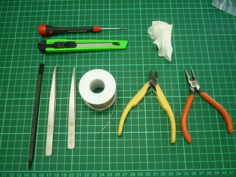
What you’ll need (at a minimum):
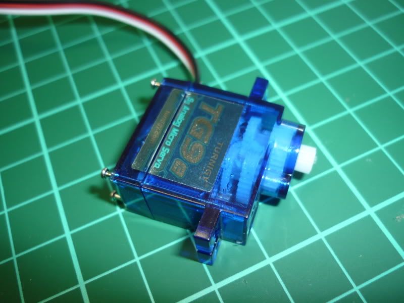
- tg9e or towerpro 9g servo/s *note this tutorial could be used for other servos, however the method of hacking may change.*
- Micro Side Cutters and Long Nose Pliers
- Fine Phillips Head Screwdriver
- Soldering Iron, with a fine tip and some thin solder to suit and a damp tissue to wipe the tip
- Box Cutting Knife
- 1.5mm Drill Bit
To replace the potentiometer in the circuit you will need two 2.7K resistors (more below).
What is *really* useful to have:
- Drill Press
- Sharp, Fine-tip Tweezers
- Hold down/ tweaking stick
- Some kind of circuit board holding jig, I simply used an alligator clip soldered to some brass
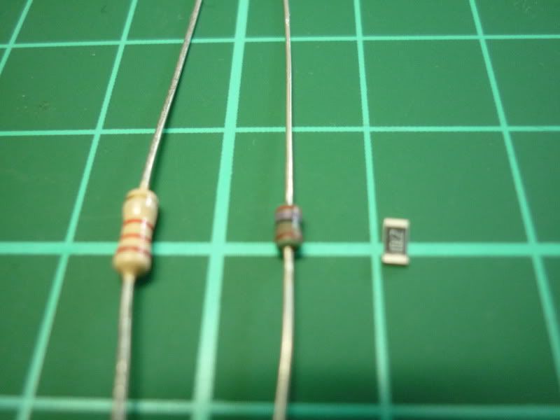
To get a servo which centers as accurately as possible, you should source accurate resistors. You also want the smallest available, to fit them into the servo’s case. For my mods I chose 1206 SMD resistors. These resistors are SMALL, and if you’re not used to dealing with tiny delicate components, try not to get too frustrated! 1206 is also a fairly large resistor as far as surface mount technology is concerned, if you have a servo with pads even closer together, you could get away with even smaller resistors (I would recommend 0805 size but I only had 1206 on hand).
Comparison of 1/4W vs 1/8W vs 1206 SMD resistors (so tiny the macro function refused to even focus…)
On with the tutorial…
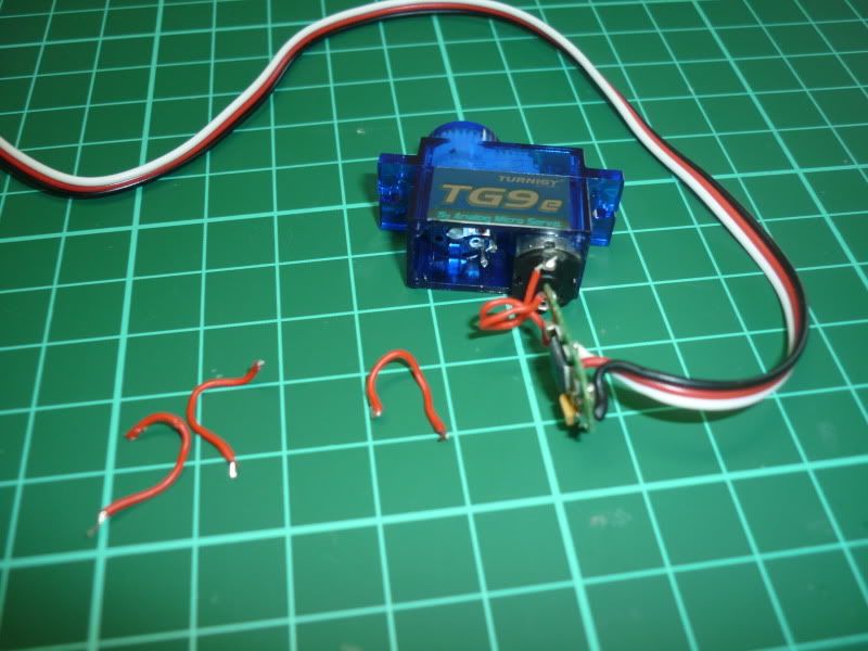
Crack open the servo by slicing the foil sticker on both sides along the join, and unscrew all four case screws. This obviously destroys any possible ‘warranty’ these $2 servos may have had… haha hobbyking warranty…
Gently lift out the circuit board and identify the three metal prongs of the potentiometer. This is the normal method the servo uses to find its position. We only want the pot as a shaft from now on so cut off as much of the prongs as is convenient, and then de-solder the wires from the circuit board (heat up the pad while constantly lightly tugging the wire till it just falls out). Needless to say don’t melt the board with too much heat, you only need a split second before the solder is molten! Wipe the irons tip often with a damp tissue to keep it clean.
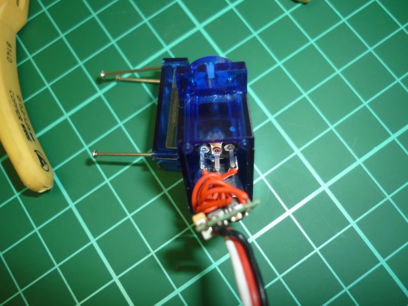
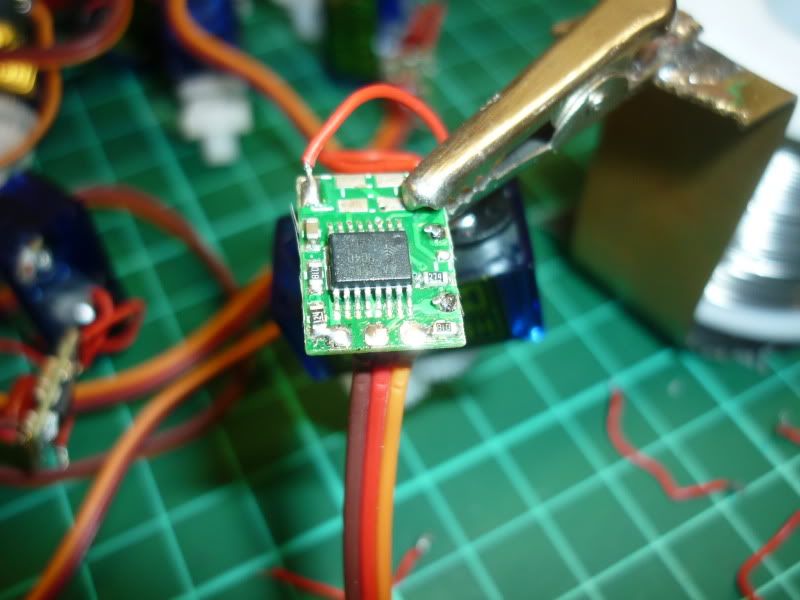
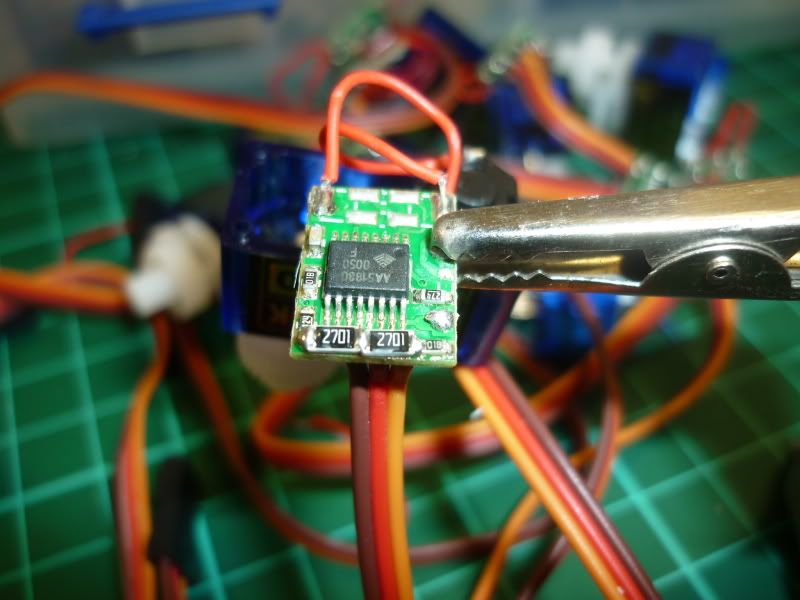
Next is to replace the potentiometer pins with the resistors. Depending on the board this may change (being hobby king, very likely it will). The trick to soldering any surface mount component is to melt the solder on one pad and push the component into place. You are then free to nicely solder the other end, and then retouch the original end. This mod looks awful but is ultra compact and very strong. Be careful however not to bridge any of the other components with solder… I do the one on the left first, then the one on the right and make sure the joins have proper continuity.
There, that’s the electronics sorted… DO NOT TURN THE SERVO ON YET, it’ll rotate brainlessly and then jam, and break/catch fire.
Luckily, the hardware portion of the mod is a piece of cake…
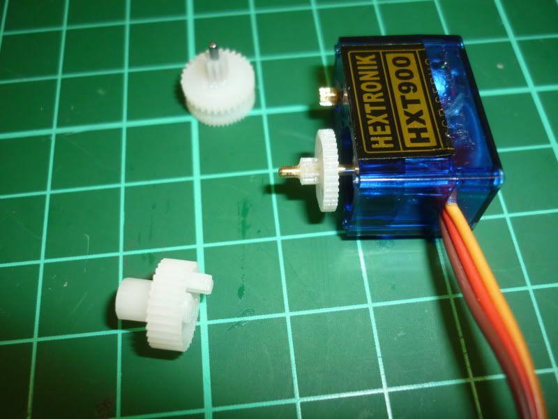
You want to pull off the output gear, so that you can drill its center hole out a little. They are pressed on HARD and it massive hurts your fingers pulling them off, but I wouldn’t recommend using any tools, you’ll probably damage the delicate teeth. Just rotate them and pull… They do pop off.
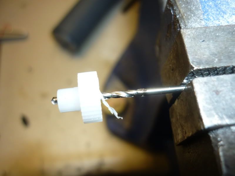
With the output gear removed, use the 1.5mm drill bit to expand the center hole. The easiest and best way to do this is just by clamping a 1.5mm bit in a vice and screwing the gear on by hand, the plastic is way soft and this is much safer than attempting to use a drill press on such a tiny workpiece!
With the hole bored out, all that’s left to do is remove the little stopper on the underside of the output gear. The box cutter or side cutters make light work of this, just make sure there is no material left protruding further than the teeth, otherwise it will still jam up. Also be warned, these little bits ping off chaotically, wear safety glasses or else!
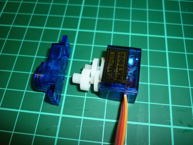
Now all that's left is to reassemble the gear train and put the screws back in!
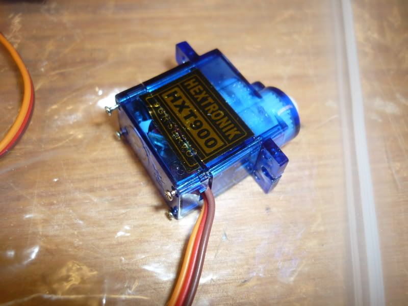
And… that’s it! If you apply power to the receiver now you should have a fairly controllable little gearmotor. Using the original gear ratio means the rotation is sluggish, but reliable. Next will be an introduction into the speed modding of these servos, which is annoying but worth it…
There are no comments on this page. [Add comment]