|
|
Glen
Experienced Roboteer

Joined: 16 Jun 2004
Posts: 9481
Location: Where you least expect


|
Glen's CNC mill build
Couple of people have asked me to document this build of my CNC machine, so here goes  Will probably be slow to update it but we'll get there in the end! Will probably be slow to update it but we'll get there in the end!
The Donor Mill
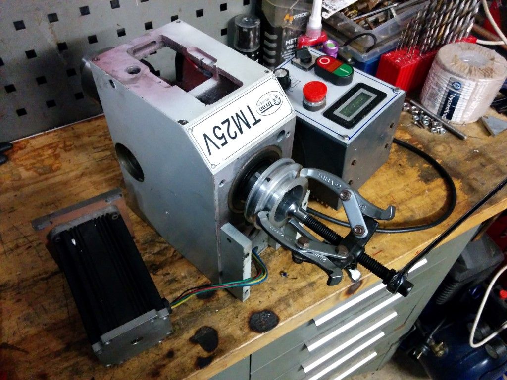
The mill itself is a Titan machinery TM25V that cost about $1800 delivered with quite a few parts included as standard. Seems to be a good combination of size, capability and price having used it for a while now. No regrets thus far!
The Tm25v is kind of a bitsa. There are many mills out there of slightly different specs to each other. The g0704 by grizzly is the popular american version but there are substantial differences to mine even though the underlying architecture is similar. Things like the way the column mounts etc etc..
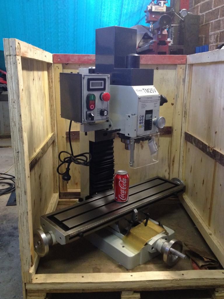
The optimum BF20L is the most similar, The only difference is the titan comes ready to go with a basic V belt drive kit and with some upgrades from the factory to use the best selection of parts amongst all the clones. An r8 spindle and so on where the others have a shitty MT2. I beg you to only get the R8 taper machines if you want one. They are just so much nicer than the morse tapers to use.
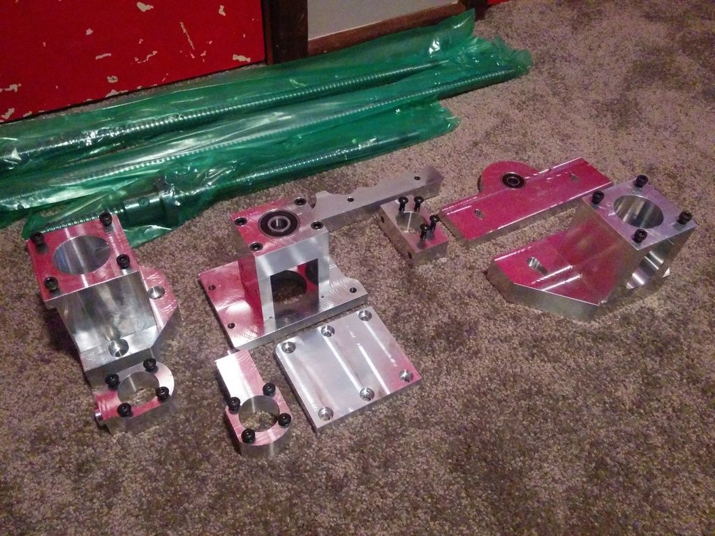
Conversion Kit
Totally wussed out on making it myself and bought the mechanical parts pre-made given the goal is to be making chips ASAP. The kit is made by a fellow in Melbourne, cost was $900, very reasonable given the quality imho and it came with all the ballscrews cut to size, All the fasteners, bearings and couplers. Amazingly made and totally happy with it so far.
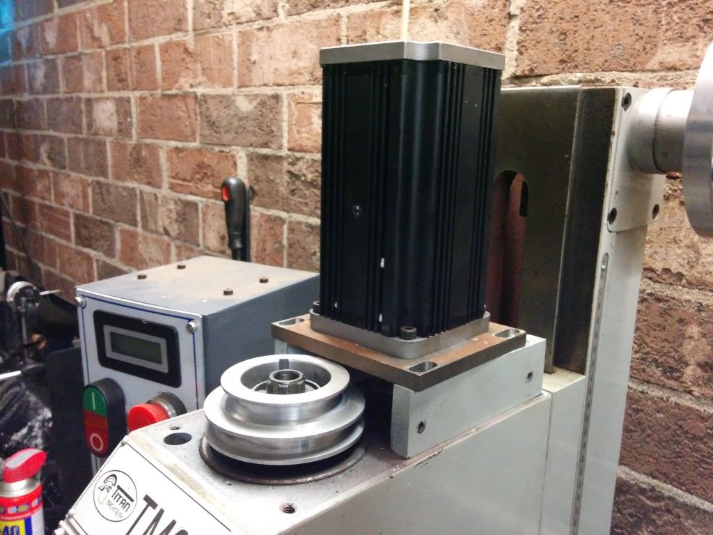
Steppers
The kit was made to fit the Nema 23 steppers so i went with the 570 oz-in torque versions. They seem to be what most are using and are also the biggest 23 size steppers. You trade off speed for torque in steppers but they still appear to be well matched based on what i've seen on other builds. The automation tech versions also have lower inductance then some of the ebay models which means more speed can be had from them.
Here's a quick run down on the basics of steppers and so forth from gecko -
http://www.cnczone.com/forums/gecko-drives/52090-cnc.html
http://www.automationtechnologiesinc.com/products-page/nema-23/nema23-570ozin-5a-14%E2%80%9D-dual-shaft-stepper-motor-kl23h2100-50-4bm
Stepper Drivers
Now this is the leap of faith. The Gecko drivers are awesome, i have the G540 in the laser cutter (thank you Angus :3) and love it, but it only does up to 3.5 amps. The steppers i have need 5 amps.
There is a 3.5 amp version of it but the inductance is very high, so that isn't ideal. I ended up getting the MX 3660. Essentially a chinese built gecko 540 on steroids. The unit is 3x single channel stepper drivers plus a break out board all integrated into the one case, making the lot substantially easier to get wired in.
This one does 10 more volts and double the amps. Plus many that have reviewed it say the control is just as smooth if not better than the Gecko. Being Chinese made we will have to see how it fares in the long run...
http://www.automationtechnologiesinc.com/products-page/digital-stepper-motor-driver/3-axis-dsp-based-digital-stepper-drive-max-60-vdc-6-0a
Power Supply
This was surprisingly tricky. The steppers require about 50v for max performance, but also based on gecko's FAQ around 12 amps. That is quite a bit of power. Most of the new ebay PSUs are 12 amps dead on and also cost $300. Definitely wanted some more amps from the PSU just in case.
Cheers to Jake and Andrew for putting me onto the right track, turns out Telecom equipment runs on 50v, so i found a brand new TDK FPS1000 50v 20 amp power supply for $100 new from Israel of all places. Surprise surprise it arrived.
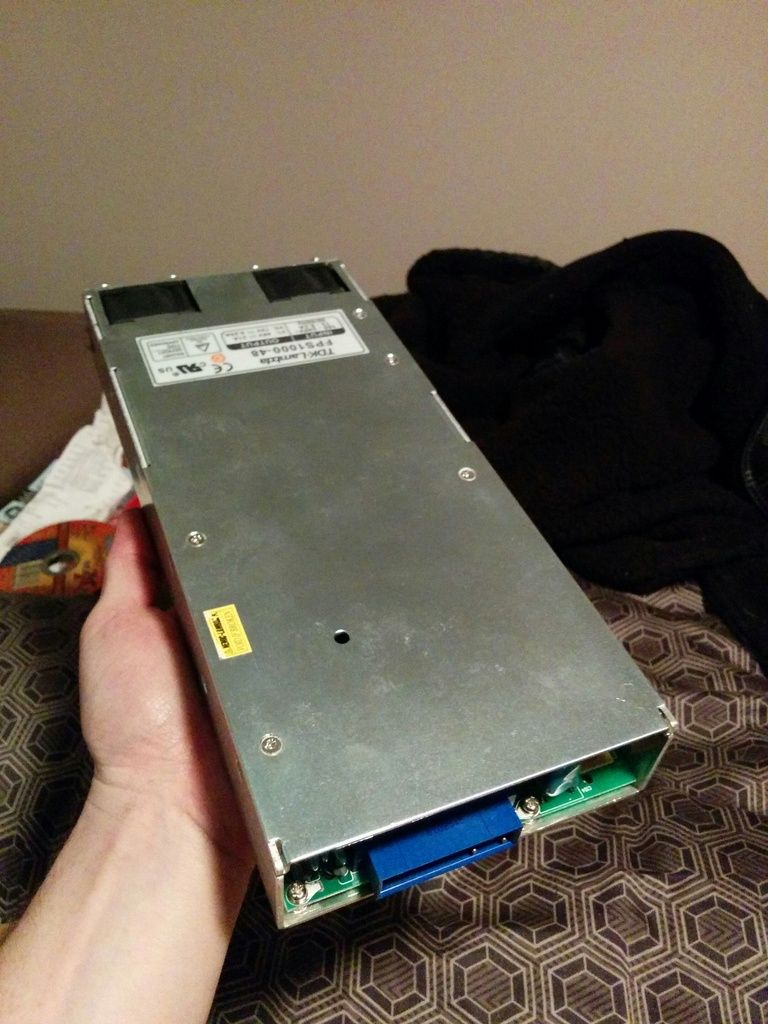
Will need to solder my own wires on to the board direct but otherwise it's perfect. These also have an i2c output so i might hook up an LCD so i can read off the output voltage, current, temperature etc. Someone else has already managed to do that -
http://electricmotorcycleforum.com/boards/index.php?topic=3949.0
Computer bits
Haven't looked into this too much yet, but i scored a handful of mini-ATX boards that were getting thrown at work, so will look to use those most likely. Otherwise it all should be fairly standard fare..
Will look into getting a proper CNC pendant and the like also.
So that's the intro I am a fair way down the track with getting the kit bolted on. Being a chinese mill nothing really lines up so there is lots of modifying as to be expected. Will post up more as things come together.
Cheers.
_________________
www.demon50s.com - Minimoto parts
http://www.youtube.com/user/HyzerGlen - Videoooozzz
|
 Tue Jun 16, 2015 12:44 am
 |
|
|
|
|
|
|
|
|
|
|
|
|
|
|
|
|
|
|
|
|
|
|
|
|
|
|
Glen
Experienced Roboteer
Joined: 16 Jun 2004
Posts: 9481
Location: Where you least expect
|
The Teardown
Only have some random pics that i took for reference so hopefully they make sense to y'all.
The motor and belt drive, Rough but functional. The angles on the pulleys aren't great and the belt is cheap garbage so i might just remake them as stated.
Ugh, its all hardwired.
Genuine mitsuboshi belt!

The head comes off - i previously drilled it to accept 3x mounting bolts instead of the 1 it originally had.
Pulleys off
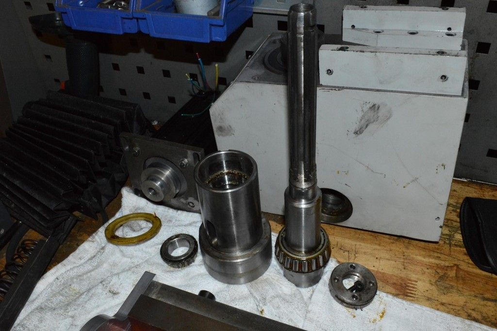
Quill mechanism. The outside sleeve runs in a pair of huge bearings you can see, the inner splined part has a giant spring under it as well as that inner shaft that acts as a cap. The spring will get replaced with an aluminium spacer to make it all solid.
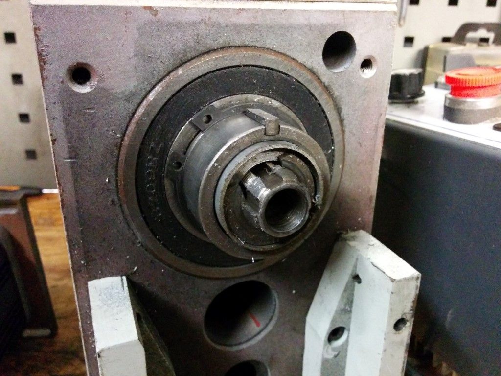
And the parts - the quill itself runs on tapered roller bearings, Replacing those with some VXB angular contacts. The nachi versions are $170 each.. At least they are easy to swap out later on should those be needed.
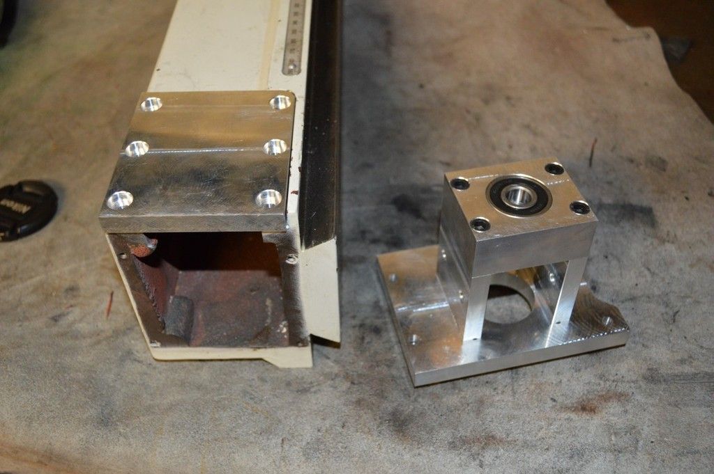
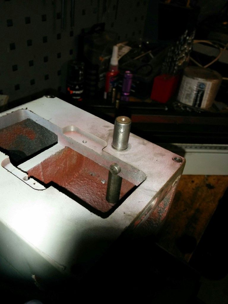
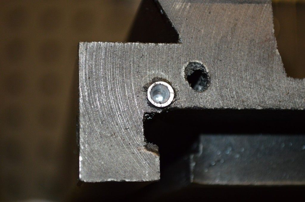
Getting to work on the Z axis parts. Get used to this shyte! No one can drill a hole straight in china so they just mash them in where ever, then bung roll pins in. Gotta drill em all out.
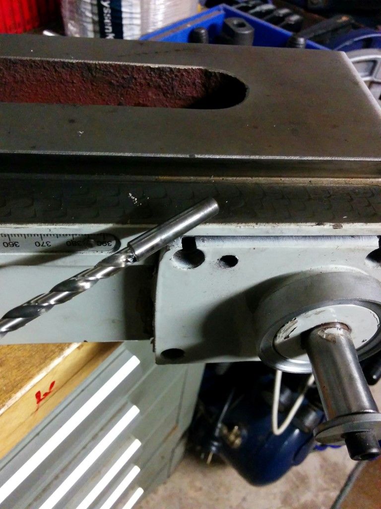
All removed, Observe the accuracy of the holes and roll pins.
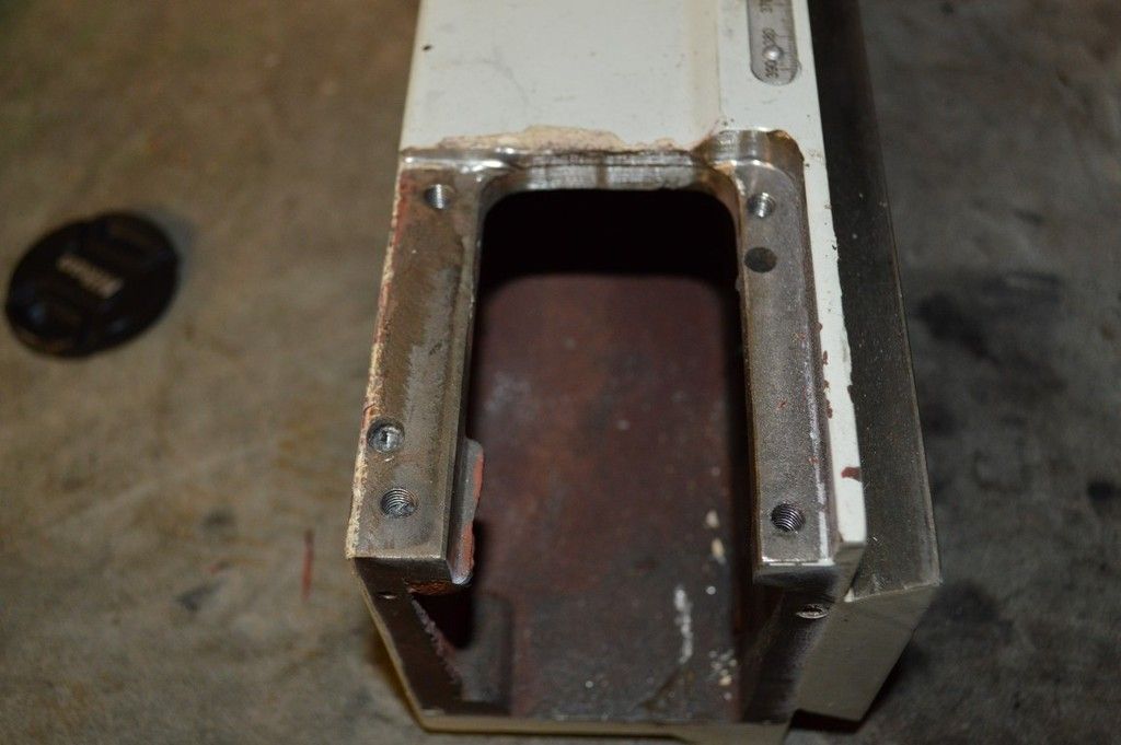
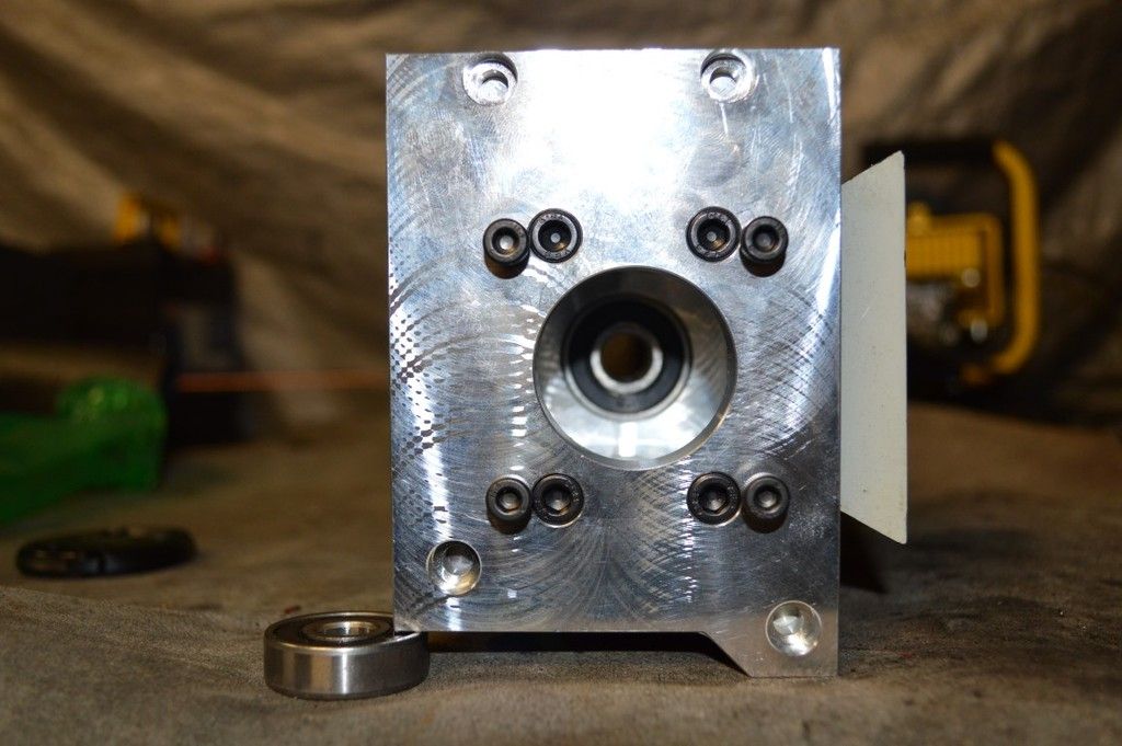
Only one of the holes lines up, theres two extras to drill myself. At this stage the plan is to mill them out to fit and use some chunky custom washers instead of having it recessed.
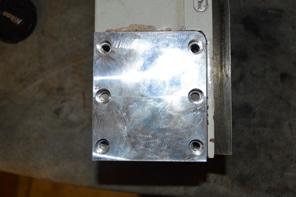
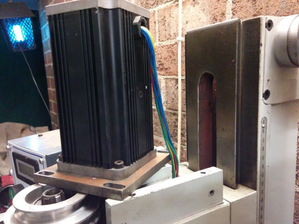
Rest of the Z axis. Have to mount the side plate shown above, then mill that to height, once thats done the 4 holes for the top part can be drilled and tapped.
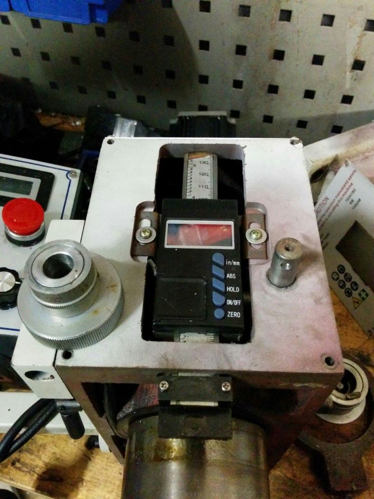
Back to the head, got to remove all the superfluous bits. The spindle DRO isn't needed since it will be locked into place.
Oh lawdy 
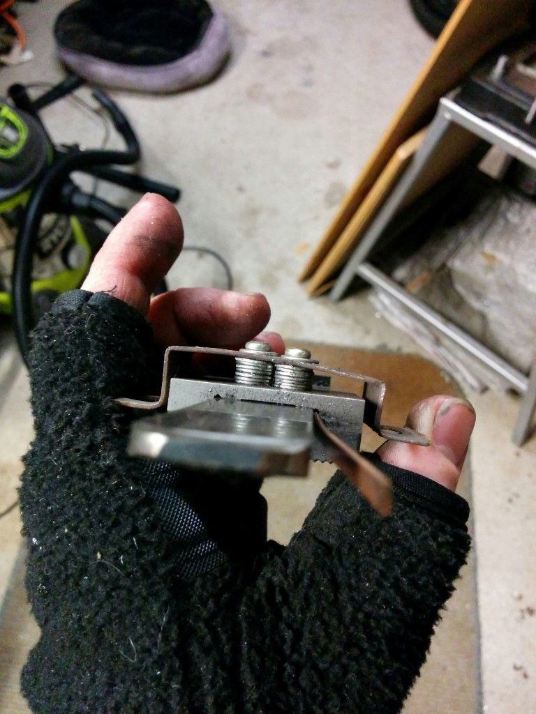
The spindle fine adjustment rack. Actually made quite well compared to the X2, but won't be needing that either.
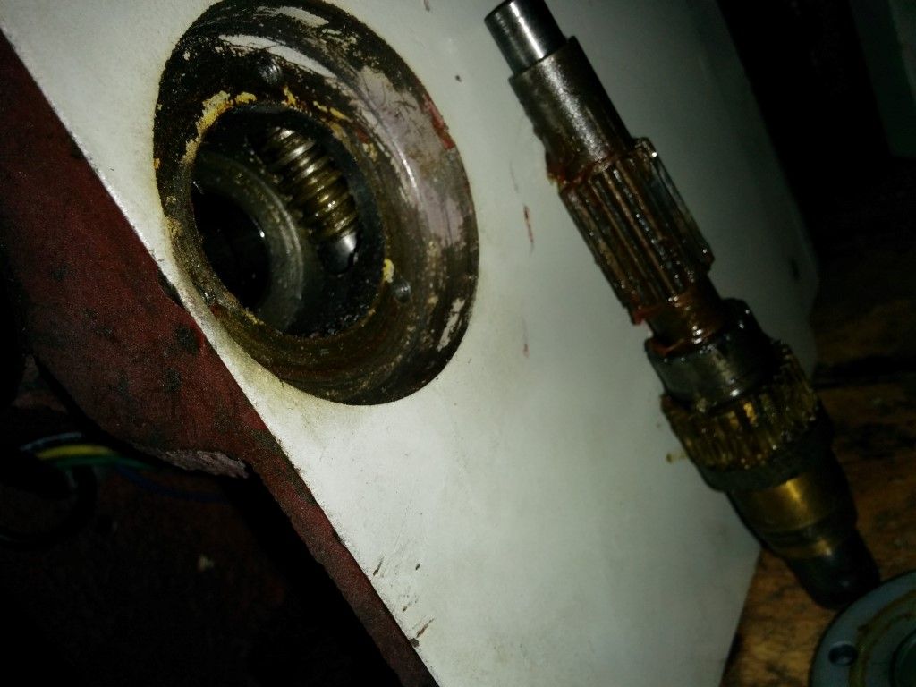
This was just wierd.. That is the shaft that runs the worm gear for the quill feed, but its retained by a roll pin they have hand tapped the end of. Why would you do that? just use a bolt!
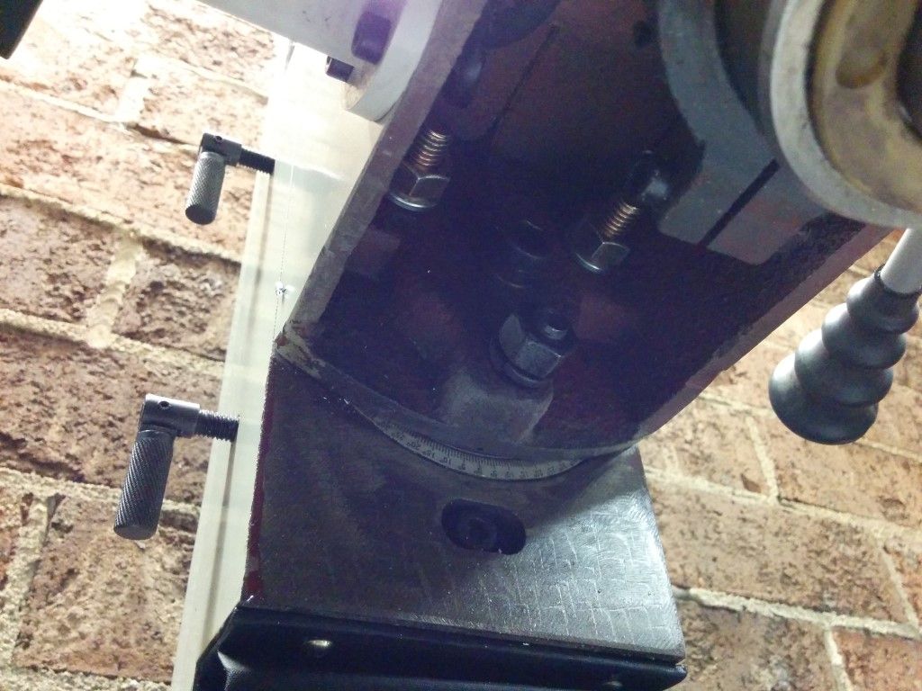
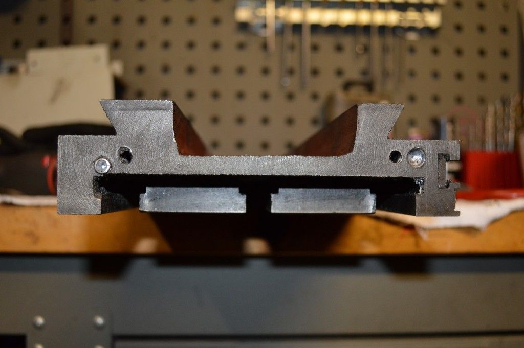
Time to get the table off. Here's the X axis setup complete with "nut that doesn't do anything to reduce backlash just makes it harder to turn". The Y axis then gets removed leaving the base ready for CNC'age 
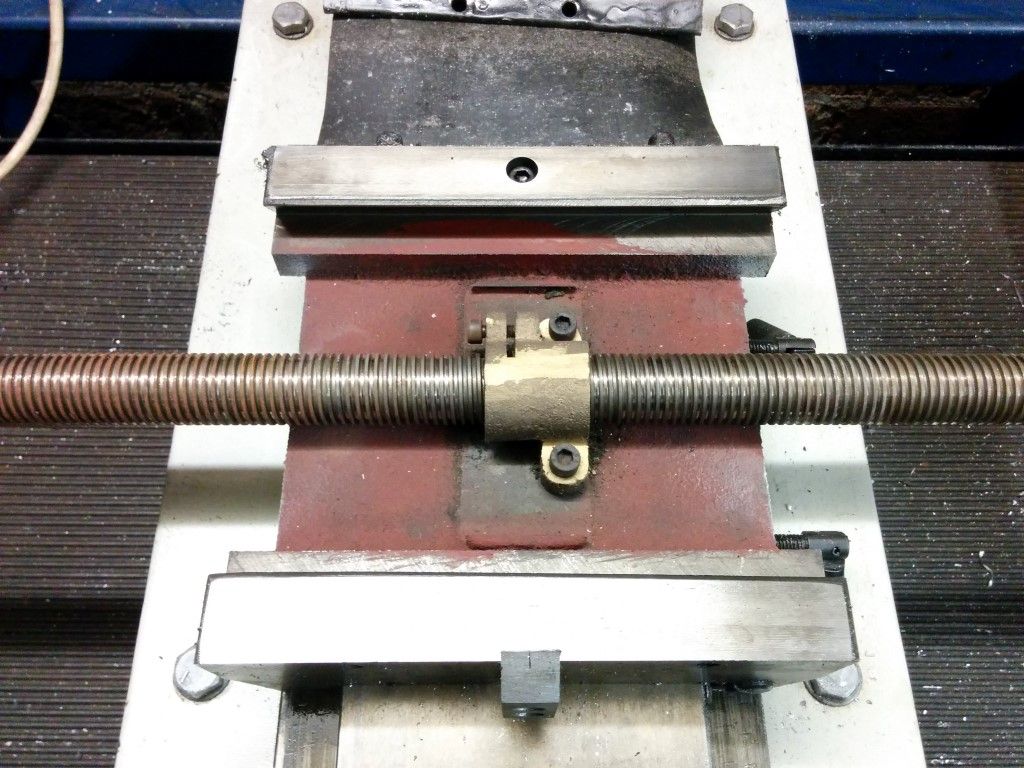
The rest of the prep is drilling more of those bastard roll pins out. Extracting them is a painful process so i just drilled them out flush and left it at that. Such accuracy. China Pls.
Shall post more on the mocking up and modding of parts tommorow
_________________
www.demon50s.com - Minimoto parts
http://www.youtube.com/user/HyzerGlen - Videoooozzz
|
|
Wed Jun 17, 2015 11:59 pm |
|
|
|
|
|

 RoboWars Australia Forum Index
-> Technical Chat
RoboWars Australia Forum Index
-> Technical Chat


