www.robowars.org

RoboWars Australia Forum Index -> Technical Chat

a few design questions...
Goto page Previous  1, 2, 3, 4, 5  Next

Post new topic   Reply to topic
  Author    Thread
Karmond


Joined: 16 Jun 2004
Posts: 97


 Reply with quote  

Warning: Long post ahead!

I just want to say that I wrote this post in peices so it does go on for a bit, some parts include questions and some parts are just minor notes. Also where I say bot, I mean design. It's far from becoming a reality, but the more I learn the better it'll be. I want to thank those who've replied and appreciate any helpful suggestions. Some design features may seem foolish to you, so feel free to point them out (even the use of skirts again).

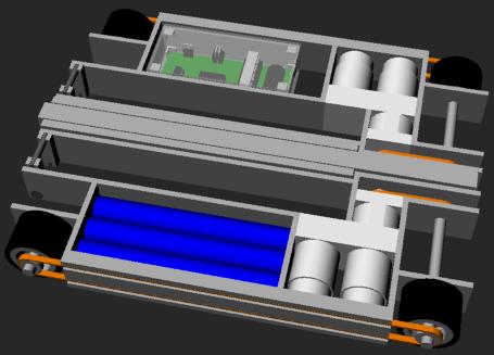
I drew about half of it (inner frame, motors, gearbox, wheels, cells) in Rhino 3D and I realised I wasn't able to fit everything in the width I had originally set aside, so to try and minimise width and avoid making it look like a square I changed the battery packs to be flat, 3 rows of 4 cells end to end. This gives them some space top and bottom (previously they were a valley style brick). This also made the bot longer, and it's now approx 400mm by 320mm + width of the side armour.


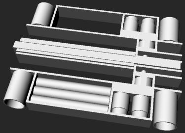
(Lifter arms are wrong, I just made them that size to see what was the largest length that would fit.)

I mentioned to Glen on Saturday that the best way to have a linear actuator fit would be if it was straight (unlike actuators which have the motors running parallel or at right angles with the cylinder). In the current design there's about a 300mm by 40mm by 40mm space for it. The actuator will need to be hinged around where the gearbox for the motor is. An advantage for having it this long is that the motor (which would be the largest part if I use a RS550) would pivot only 1/5 of the height of what the end of the actuator pivots. This essencially stops it from hitting the top and bottom.

Actuator construction I'm still in the dark about, I don't know what's required in terms of bearings, switches, cylinder thicknesses etc. I would also like to know if the following is possible, and bear with me as I know little about electronics: I want to have one of the AUX outputs extend the actuator until it reaches point B, where a switch is triggered and the actuator stops extending. If there is no AUX current flowing the actuator retracts until point A where a switch is triggered and the actuator won't retract further.

I'm guessing that the actuators will probably be the main roadblock in this design.

Prior to drawing the bot I realised that the left side and the right are only connected by the rear armour, the base and the lifting mechanism so I'll need to use something tough for the base or the bot will end up very warped after a good knock. First thought was 1.8 mm Titanium for the base which admittedly would be very expensive.

Another thing I picked up from the event on Saturday was that polycarbonate will suffice for the top so I'll use 3mm for that.

I'll need to source some gears for the dual gearboxes, I'll need 6 spur gears with a pitch circle diameter >= 19.5mm. Looking in my HPC gears catalogue I have from a few years back getting the gears from them will cost about $80 + postage... So if I can get something like that locally that would be good.

I need to enquire about the possibility of having the wheels made from aluminium tube, welding a disc inside for the axle, and gluing rubber on the outside. This of course leads to the question of whether there are good suppliers of aluminium tube around (hmm seems http://www.performancemetalsaustralia.com.au/ has some), I need one with an outer diameter of about 1.75 inches (44.45mm). If you're wondering why I have imperial measurements it's because I've been using international sources to find out what fits.

Do people buy their pulleys and belts from somewhere or make them themselves? I'd like to look into the option of using belts however The pulleys need to be under 35mm diameter, preferably the smaller the better to leave some space for wires to fit around in those tight spaces. Also how wide/long would pulleys that small need to be? I wouldn't want to go much more than 10mm if at all.

Battery Cells are currently designed as 3600 MAH NiMH.

I've decided to design the inner walls with 5mm aluminium. Mostly just to save weight as I'm unsure how much some components will weigh at the moment. Hopefully the juicy soft gooey insides of my design will be protected by a thick candy shell which I have yet to decide on.

Outer walls will almost defiantly be steel as I don't think I can use too much Titanium at this stage. Thickness depends on how much weight I'll have to spare, but for drawing reasons, I'll just go with 5 mm steel for now to match the thickness of the inner walls, and adjust accordingly later on.

I still want to use skirts; Jolts skirts impressed me even though they don't really hinge much by design. I figure if I do end up building this bot and do use titanium for the base, I could just buy a larger piece and cut some skirts from the same sheet (How hard would it be to cut 1.8 mm Titanium anyway?)

Lifting mechanism I haven't put much thought into but I think I'll need to use steel for all of it. The arms could maybe be the same thickness as the outside walls to save money? I'll probably need to go box section steel for the lifting bar also. I'm not sure what are common sizes and how available they are but I'll need something about 1.5 inches high (38.1 mm). Rectangle section would be even better if it's available and if I could get 1.5 inches (38.1 mm) by 0.75 inches (19.05 mm) that would be ideal. The rods/axles would also probably need to be steel but I don't know about the thickness, something like 5 or 6 mm would probably be good but I'm not sure if that's thick enough to support the lifting mechanism. Anything much larger would look a little bulky as the bot isn't very tall.

Um, I've probably missed something along here somewhere but any comments would be appreciated.

Post Tue Apr 03, 2007 8:50 pm 
 View user's profile Send private message
assassin


Joined: 27 Jun 2004
Posts: 1105
Location: SunshineCoast


 Reply with quote  

Sounds like a lightweight? Do you expect to fit this under 13.6Kg? If you do it looks like it's going to cost you a lot of money in fancy materials(titanium etc).
_________________
Imagination is more important than knowledge. Knowledge is limited. Imagination encircles the world.
Albert Einstein.

Post Tue Apr 03, 2007 9:16 pm 
 View user's profile Send private message Send e-mail
Karmond


Joined: 16 Jun 2004
Posts: 97


 Reply with quote  

quote:
Originally posted by assassin:
Sounds like a lightweight? Do you expect to fit this under 13.6Kg? If you do it looks like it's going to cost you a lot of money in fancy materials(titanium etc).
I'm not solid on titanium yet due to the cost.

As for the weight I've yet to calculate it but I can drop stuff to save weight if needed (in fact, using 2 motors for drive instead of 4 will save me a bit of money and complication). I've only made rough guesstimations; 4kg for drive, 1kg for batteries, 2kg for actutors. leaving 6.6kg for the frame, armor and lifting mech. If I made the side armor out of 4mm stainless I think that's less than 2kg. The ali walls inside would be less than that I'd hope (1.2kg for every 2.3m of ali wall?). 3mm polycarb is pretty light also. Maybe I've crammed too much into this but like I said I can change things when I start designing in detail.

Post Tue Apr 03, 2007 9:32 pm 
 View user's profile Send private message
Nick
Experienced Roboteer


Joined: 16 Jun 2004
Posts: 11802
Location: Sydney, NSW


 Reply with quote  

I have some thick wall ali tube in 40mm diameter; could you use thicker tread? From my experiences with a four wheel bot with 50mm wide treads, your wheels are probably wider than they need to be. My bot did NOT like turning and basically hopped from wheel to wheel as it skid-steered. that wastes a heap of battery power and is harder on your gearboxes. For a 4 wheel design, I would go 25 to 35mm wide tread, unles the tread is hard & slippery.

I'm still not quite sure how the actuator fits in the design - can you write a bit more about that? Is it a four bar lifter mechanism? You can probably get by with aluminuim for most of the lifter and just use steel at the end for bash protection - the flippers in QLD use aluminium arms and have no problems.
_________________
Australian 2015 Featherweight champion
UK 2016 Gladiator champion

Post Tue Apr 03, 2007 9:54 pm 
 View user's profile Send private message
assassin


Joined: 27 Jun 2004
Posts: 1105
Location: SunshineCoast


 Reply with quote  

Sorry I don't know but is this your first bot? Are you confident you can design and build this to meet NSW standards? The reason I ask is, I wouldn't like to see you spend so much time and money and then meet you first spinner and this happens: http://www.youtube.com/watch?v=ifBLBYwxe2Q or would I Laughing thats a good vid!

Its a real neat bot, build what you want to build but be realistic too. This may only come with experience, which might be why your asking the questions. So are you sure you can build this underweight and reliable?
_________________
Imagination is more important than knowledge. Knowledge is limited. Imagination encircles the world.
Albert Einstein.

Post Tue Apr 03, 2007 9:59 pm 
 View user's profile Send private message Send e-mail
Karmond


Joined: 16 Jun 2004
Posts: 97


 Reply with quote  

quote:
Originally posted by Nick:
I have some thick wall ali tube in 40mm diameter; could you use thicker tread?
Yeah, I hadn't done research on the rubber yet, but you can always use something thicker than what you need and trim it down slightly, right? The number I threw out was just the best fit from a selection of sizes from The Robot Marketplace which is all imperial measurements.
quote:
Originally posted by Nick:
From my experiences with a four wheel bot with 50mm wide treads, your wheels are probably wider than they need to be. My bot did NOT like turning and basically hopped from wheel to wheel as it skid-steered. that wastes a heap of battery power and is harder on your gearboxes. For a 4 wheel design, I would go 25 to 35mm wide tread, unles the tread is hard & slippery.
Ok, good point, it had crossed my mind but since the wheels are so small I wasn't sure there'd be alot of grip. The wheels are really only that wide to fill out the space but making them smaller wouldn't be that much of an issue. 35mm is about half as wide as they are currently.

quote:
Originally posted by Nick:
I'm still not quite sure how the actuator fits in the design - can you write a bit more about that? Is it a four bar lifter mechanism? You can probably get by with aluminuim for most of the lifter and just use steel at the end for bash protection - the flippers in QLD use aluminium arms and have no problems.
I'm not even quite so sure myself. :p Basically I'm hoping I could make an actuator that's straight in design, so it goes from a motor, to a gearbox (ring gear like the banebots [36mm gearmotor]) to a threaded rod. No belts or 90 degree gears like most actuators. The actuator would need to be hinged on the sides about where the gearbox is.

The lifting mech would be almost identical to Biohazard which you can get info from here . Although there would be differences with the actuators an how they pivot.

That's good to know about the ali, I was worried about spinners warping the lifter.

quote:
Originally posted by assassin:
Sorry I don't know but is this your first bot? Are you confident you can design and build this to meet NSW standards? The reason I ask is, I wouldn't like to see you spend so much time and money and then meet you first spinner and this happens: http://www.youtube.com/watch?v=ifBLBYwxe2Q or would I Laughing thats a good vid!

Its a real neat bot, build what you want to build but be realistic too. This may only come with experience, which might be why your asking the questions. So are you sure you can build this underweight and reliable?
It would be my first, and I know it's more complicated than it should be... But I'm not going to attempt to build this if I don't think I can.

As for that video, did you intentionally use one of the bot I'm basing my design on? :p Did you realise that Biohazard would probably be the most successful heavyweight ever? As for having it trashed, maybe... but how many featherweights in Australia have kept going in a single match until they have 4 sides ripped off, alot of the matches and videos I've seen has the drive/radio/battery fail before any major damage is done and the bot is spared.

P.S. Australia has no Full Body Spinners. :p

Last edited by Karmond on Tue Apr 03, 2007 10:37 pm; edited 2 times in total

Post Tue Apr 03, 2007 10:15 pm 
 View user's profile Send private message
Glen
Experienced Roboteer


Joined: 16 Jun 2004
Posts: 9481
Location: Where you least expect


 Reply with quote  

at a glance the wheels are much too wide for the sort of motors behind them. my drill powered robots get away nicely with about 25mm of tread on two wheels so that with 4 would be fine.

about the connection between the sides of the frames you could always keep the shaft solid on the lifter and use that as a main connection point.

with the actuator unless you want to buy something you could always just use a length of threaded rod but instead of having it so long use a piece of tube with a pair of nuts welded into each ends and use that as part of the actuator. that way it will effectively be half length when retracted. andrew uses that method on sproing. works good for keeping things compact.

or you could try something like a scissor jack in a car they pack down fairly flat. (the diamond shaped ones).

about the belts you can buy timing belts in really small diameters, cant recall were but jeffs in late are a good example. smallparts.com?


quote:
(How hard would it be to cut 1.8 mm Titanium anyway?)


not too bad with a grinder and a few disks if you just need a couple of small ish offcuts Smile

wrt the lifter if you expect it to take any hit it needs some ability to twist and go back to its original shape (rubber mounts or some such) or at least be able to get bent and still work. if aaron still has pics of his axe robot he can probably put some pics up, the axe on that thing could bend a huge amount side to side.
_________________
www.demon50s.com - Minimoto parts
http://www.youtube.com/user/HyzerGlen - Videoooozzz

Post Tue Apr 03, 2007 10:24 pm 
 View user's profile Send private message Send e-mail Visit poster's website MSN Messenger
Nick
Experienced Roboteer


Joined: 16 Jun 2004
Posts: 11802
Location: Sydney, NSW


 Reply with quote  

The 1Kg estimate for the batteries is good; the cells themselves would be about 820 grams.

The two wheels on Jolt are 25mm wide by 60mm diameter and they allowed me to push Ya Mum and Broken around with ease. Jolt is absolutely NOT a pushy bot, so 4 x 35mm wide wheels with a soft tread should do the trick for you. You might ask Russel aboutthe conveyor belt material he has, or about casting urethane tyres. I really like smal diameter wheels - they are harder to hit. light and fit into designs easily Very Happy

For the actuator, i would look at a Banebots gearbox (like you said) and add an exta bearing housing on the end to take the thrust loads. you can use a ball screw for efficiency like Biohazzard :


or ACME threaded rod to save money:


The threaded rod loses around 40% of the motor's power in friction; you can see why Carlo went for Ball threads in Biohazzard! A 3 foot length of 1" acme thread is under $20 US. Either way, you would have to get the end of the rod machined to couple it to the motor and run in a bearing.

If that sounds too hard to make, I have an easier but heavier option. If you are interested, I can draw it out; its hard to put into words Wink
_________________
Australian 2015 Featherweight champion
UK 2016 Gladiator champion

Post Tue Apr 03, 2007 10:46 pm 
 View user's profile Send private message
Karmond


Joined: 16 Jun 2004
Posts: 97


 Reply with quote  

quote:
Originally posted by Glen:
about the connection between the sides of the frames you could always keep the shaft solid on the lifter and use that as a main connection point.
Yeah but the connection is only at one point and that's were the arms meet the bar which is around the middle.

quote:
Originally posted by Glen:
with the actuator unless you want to buy something you could always just use a length of threaded rod but instead of having it so long use a piece of tube with a pair of nuts welded into each ends and use that as part of the actuator. that way it will effectively be half length when retracted. andrew uses that method on sproing. works good for keeping things compact.
Possibly, I've got alot of length to to fit it in.

quote:
Originally posted by Glen:
or you could try something like a scissor jack in a car they pack down fairly flat. (the diamond shaped ones).
If you mean what I think you mean I don't think that'll fit in the design.

quote:
Originally posted by Glen:
wrt the lifter if you expect it to take any hit it needs some ability to twist and go back to its original shape (rubber mounts or some such) or at least be able to get bent and still work. if aaron still has pics of his axe robot he can probably put some pics up, the axe on that thing could bend a huge amount side to side.
Rubber mounts? : / If I wanted it strong I thought it was supposed to be solid and smoothe, not flexable. You might need to elaborate...

If what Nick says is true and I can use aluminium then any flexing would be limited to hopefuly the lifter bar mainly and I assume would be easily replacable.

quote:
Originally posted by Nick:
The threaded rod loses around 40% of the motor's power in friction; you can see why Carlo went for Ball threads in Biohazzard! A 3 foot length of 1" acme thread is under $20 US. Either way, you would have to get the end of the rod machined to couple it to the motor and run in a bearing.

If that sounds too hard to make, I have an easier but heavier option. If you are interested, I can draw it out; its hard to put into words Wink
That sounds good, I'm interested in any working option. But do you think it'll fit in the space? Is the 1" measurement the diameter of the rod?

Last edited by Karmond on Tue Apr 03, 2007 11:00 pm; edited 1 time in total

Post Tue Apr 03, 2007 10:51 pm 
 View user's profile Send private message
Nick
Experienced Roboteer


Joined: 16 Jun 2004
Posts: 11802
Location: Sydney, NSW


 Reply with quote  

Biohazzard used a four bar linkage on the lifter arm - very cool and effective!

I would atill make the end of the lifter from steel and / or titanium - anything that might be hit needs to be tough.
_________________
Australian 2015 Featherweight champion
UK 2016 Gladiator champion

Post Tue Apr 03, 2007 10:58 pm 
 View user's profile Send private message
Karmond


Joined: 16 Jun 2004
Posts: 97


 Reply with quote  

quote:
Originally posted by Karmond:
I would also like to know if the following is possible, and bear with me as I know little about electronics: I want to have one of the AUX outputs extend the actuator until it reaches point B, where a switch is triggered and the actuator stops extending. If there is no AUX current flowing the actuator retracts until point A where a switch is triggered and the actuator won't retract further.
I've changed my mind on this. While I'll still need the switches, having only one input for the actuator will cause issues if there's a problem and the actuator can't retract all the way to the switch. Also I wouldn't be able to set the lifter to a particular height if I wanted to, dunno why I would though.

Post Wed Apr 04, 2007 3:08 pm 
 View user's profile Send private message
Karmond


Joined: 16 Jun 2004
Posts: 97


 Reply with quote  

Was bored:


I also noticed that if I do go with the dual motor gearbox setup I could just not get a banebots gearmotor and just go for spur gears. This will save space, a small amount of money, and since I needed a reduction like 9:1 because the wheels are so small, I'd need a special order from banebots anyway or I would have had to order a 27:1 and 16:1 setup and combine the two. However going with spur gears would probably be harder and might be more unreliable.

Post Sat Apr 07, 2007 11:40 pm 
 View user's profile Send private message
Totaly_Recycled
Experienced Roboteer


Joined: 15 Jun 2004
Posts: 1346


 Reply with quote  

Hi
I just looked over your drawing ,it looks like you are going to go 4 wheel drive .With the set up you have drawn, haveing the wheels spaced so far apart it will have great dificulty turning and require a lot of power do to so .I cant realy make any sugestions apart fromtrying to redisghn it with both sets of wheels spaced closer together or go 2 wheel drive with castors.

Post Sun Apr 08, 2007 7:16 am 
 View user's profile Send private message
Karmond


Joined: 16 Jun 2004
Posts: 97


 Reply with quote  

quote:
Originally posted by Totaly_Recycled:
Hi
I just looked over your drawing ,it looks like you are going to go 4 wheel drive .With the set up you have drawn, haveing the wheels spaced so far apart it will have great dificulty turning and require a lot of power do to so .I cant realy make any sugestions apart fromtrying to redisghn it with both sets of wheels spaced closer together or go 2 wheel drive with castors.
I'm assuming you mean space between the front and rear wheels, or the length of the bot as the ideal setup for wheels should be a square, right?

The centers of the wheels are spaced about 260 mm (left-right) by 330 mm (front-rear). If that's too much of a rectangle I can look into it, but my thoughts were that it wasn't that bad. If this setup wouldn't work I might be able to swap the gearbox and rear wheels around. I'd need to keep the front wheels as far forward as possible because that's where all the downforce would go when using the lifter.

Post Sun Apr 08, 2007 2:02 pm 
 View user's profile Send private message
Philip
Experienced Roboteer


Joined: 18 Jun 2004
Posts: 3842
Location: Queensland near Brisbane


 Reply with quote  

You can always start building your design and find out how it handles. Some builders have made prototypes from MDF and the like. This will allow you to test your theories and find if you are happy with the result without spending lots of money on purchasing specialized materials, cutting and welding.

Good luck.
_________________
So even the rain that falls isn't actually going to fill our dams and our river systems

Post Sun Apr 08, 2007 2:28 pm 
 View user's profile Send private message
  Display posts from previous:      

Forum Jump:
Jump to:  

Post new topic   Reply to topic
Page 2 of 5

Goto page Previous  1, 2, 3, 4, 5  Next

Forum Rules:
You cannot post new topics in this forum
You cannot reply to topics in this forum
You cannot edit your posts in this forum
You cannot delete your posts in this forum
You cannot vote in polls in this forum


Last Thread | Next Thread  >
Powered by phpBB: © 2001 phpBB Group
millenniumFalcon Template By Vereor.